






01 · Where it fits
Where heliolithography fits
There are several families of 3D printing. The two most widely used are fused deposition modeling (FDM), where a heated nozzle extrudes plastic filament along each layer, and stereolithography (SLA), where light cures liquid photopolymer resin. Other families include powder-bed fusion and binder jetting.
SLA and its relatives (DLP and masked LCD printing) are known for fine detail and smooth surfaces. Most modern desktop and professional SLA systems are “inverted” or bottom-up: the build platform is lowered into a resin tank with a transparent film at its base, and a UV laser steered by galvanometer mirrors (or a projector or LCD mask) cures one cross-section at a time through that film.
Heliolithography belongs to the same family of vat photopolymerization. It keeps what SLA does well, light-cured resin with fine detail, and changes how the part is built: rotation and continuous rise instead of discrete layers.
02 · Limits of layers
The limits of layer by layer
In a conventional inverted SLA cycle, each layer goes through the same sequence: cure the cross-section, stop, peel the cured layer away from the film, lift the platform, let fresh resin flow back (often with a wiper to recoat), lower the platform, and repeat. A tall part repeats this thousands of times.
That cycle creates well-known constraints. Time spent peeling, lifting and recoating is time the light is not curing. Peel forces act on the part and the film at every layer, which manufacturers address with flexible tanks and low-force mechanisms, and which grow harder to manage as the build area gets larger. Resin must flow back under the part between layers, which favors low-viscosity materials. Laser SLA also traces each layer point by point, so exposure time scales with the area being cured.
03 · The principle
The principle: rotation plus rise
Heliolithography uses a circular build area that revolves around a single center point. The build platform holds the part in an inverted orientation above a construction area. It rotates continuously and rises in a gradual, programmed manner, so the gap between the part and the construction area increases steadily with each revolution.
Light is directed from below into a defined exposure zone. As the part rotates through that zone, the newly exposed resin bonds to the material above it. The result is one continuous “layer” deposited and bonded in a helical fashion: a spiral, like the thread of a screw, rather than a stack of separate slices. The vertical rise per revolution sets the spiral pitch.
Because the part never has to stop and separate from the film between layers, there is no discrete peel, lift and recoat cycle. Rotation itself carries fresh resin into the exposure zone behind the cured strip.
Heliolithography compared with layer-by-layer SLA
| Layer-by-layer SLA | Heliolithography | |
|---|---|---|
| Build path | Stack of flat layers | One continuous helical spiral |
| Motion between layers | Stop, peel, lift, recoat, lower | None: rotate and rise continuously |
| Light (laser SLA) | Traces each layer point by point | Cures localized radial sectors as the part turns through them |
| Peel forces | Every layer | No layer-by-layer peel cycle |
| Resin refresh | Flows back between layers | Swept in continuously by rotation |
| Viscosity range | Favors thinner resins | Wider range, including thicker and ceramic-loaded materials |
| Build area vs detail | Larger area usually means larger pixels | Rotation sweeps a fine localized field across a larger area |
| Main speed limits | Exposure plus mechanical cycle per layer | Cure rate and rotation speed |
04 · Architecture
System architecture
Conventional vat printing runs its functions one after another: cure, separate, recoat, reset. Heliolithography distributes those functions around a rotating build surface, so different regions can cure and replenish at the same time while synchronized vertical motion builds the helical path. Mechatronic synchronization keeps rotation, vertical motion, exposure timing and resin delivery aligned. A system has five core elements:
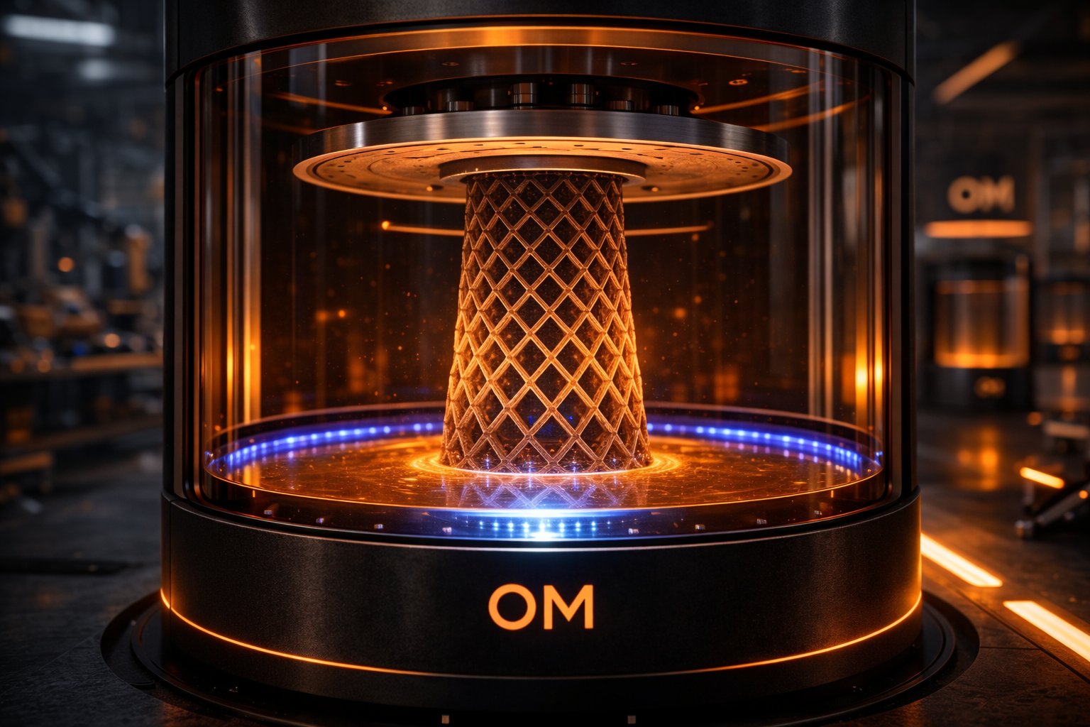
 Concept render
- Light engineHigh-power UV, laser diode or VCSEL light, projected from below into the exposure zone.
- Cure zonesLocalized radial exposure sectors, one or several around the build surface.
- Rotating build platformHolds the part inverted and turns it continuously through the exposure zone.
- Z riseLifts the platform steadily, one spiral pitch per revolution, in a programmed manner.
- Resin channelsDedicated replenishment channels between cure zones; rotation carries each region through fresh resin.
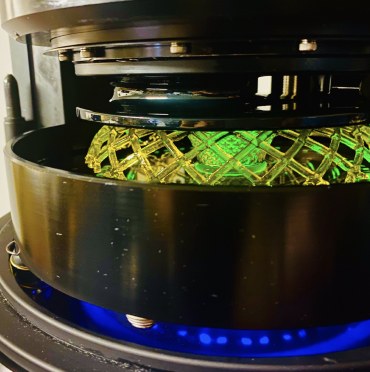
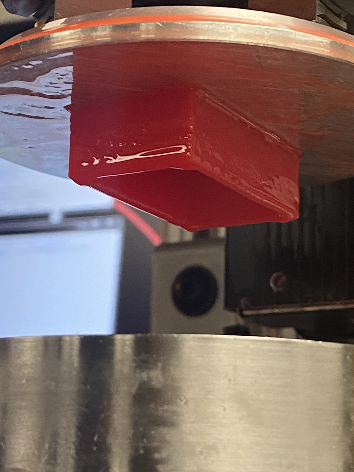
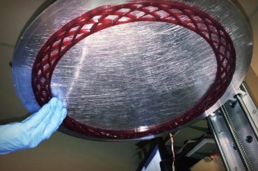
 Real prototype
05 · Material pathway
The material pathway: bringing fresh resin to the cure zone
Continuous motion only helps if the material can keep up. In inhibition-based continuous printing, an uncured interfacial region keeps the growing part from adhering to the window, but resin still has to reach the active interface. Viscosity, flow distance and the size of the exposed cross-section all affect how quickly it can replenish, which is why continuous processes have tended to favor open, lattice-like geometry.
OM’s architecture combines inhibition with polar-arranged cure zones and dedicated resin channels. As the build surface rotates, each region of the part passes through a replenishment channel before it returns to an exposure zone. The engineering objective is to replenish dense cross-sections without relying only on resin flowing inward from the outer edge, reducing the dependence of continuous printing on open geometry and broadening the usable material window. Actual speed remains a function of resin rheology, cure dose, channel geometry and motion control.
The engineering objective: replenish dense cross-sections without relying only on resin flowing inward from the outer edge.
06 · Scalable exposure
Scalable exposure: one platform, two design priorities
Because the part rotates through the light, the exposure zone does not have to cover the whole build area at once. Rotational scanning sweeps a localized exposure field across a larger build envelope. The aim is to keep fine projected detail while expanding the area that can be addressed, rather than enlarging every projected pixel. The same platform can be configured for different priorities:
| Configuration | What it does |
|---|---|
| Single radial sector | Prioritizes area and resolution. One pie-shaped exposure region scans the rotating build surface; one revolution is one helical layer increment. |
| Multiple radial sectors | Prioritizes throughput. Additional cure zones add exposure and replenishment opportunities around each revolution, supporting several layer increments per turn. |
07 · Light sources
Light sources
Heliolithography is designed to take advantage of advances in light sources rather than being tied to one. OM’s patents describe high-power UV sources as well as laser diode chips and arrays of vertical-cavity surface-emitting lasers (VCSELs), including light sources mounted on a rotary table that rotates in relation to the construction area, and cooling to manage the heat generated during printing.
Coordinating multiple tiled projectors is another route to increasing optical power across the cure zones while scaling the addressed area. Exposure calibration, tile registration and synchronized motion are essential to keeping dose and geometry consistent. Scalability is a system question: whether light delivery, material flow and motion stay coordinated as the machine grows.
As light engines become more powerful and more affordable, the cure rate available to the process rises with them. This is why OM describes the platform as printing at the speed of light: with no peel cycle, the limits are how fast the light can cure and how fast the platform can rotate.
08 · Materials
Materials and viscosity
Layer-by-layer resin printing depends on resin flowing back under the part between layers, which generally favors thinner resins. In heliolithography, rotation sweeps material through the construction area continuously. OM’s patent on high-viscosity build materials describes a viscous, solidifiable composition deposited on the construction area, with mechanisms that continuously remove excess build material not incorporated into the part.
This opens a wider range of viscosities, including thicker materials than other systems can process. That matters for filled and engineering resins, where higher filler content often means higher viscosity, and for highly loaded ceramic resins, where replenishment channels and rotational transport create a path to processing more demanding formulations. OM has also developed a dual-cure method, Photosynthesis, aimed at faster curing and zero adhesion.
09 · Prototypes
Prototype demonstrations
OM’s prototypes have demonstrated rotational printing at rates of 10 layers per second. Rate depends on geometry, material, dose and machine configuration, and patent records document the inventions rather than independently validating prototype performance.
A recurring question is whether a rotational process can produce non-circular parts. It can: the machine rotates, but the part does not have to be round. Prototype demonstrations include concentric rings and rectangular geometry made by rotation.
See the photos and footage in Real machines, real parts above. Rate depends on geometry, material, cure dose and machine configuration.
10 · Ceramic cores
Target application: ceramic cores for gas-turbine casting
Investment casting uses ceramic cores to define internal cavities in metal parts. After casting and core removal, those spaces become the cooling passages that let turbine blades and vanes operate in demanding thermal environments. Printed ceramic cores are already an established industry direction; layerwise ceramic vat systems use a rotating vat and wiper to spread slurry, while the build platform moves vertically.
In OM’s architecture, rotation plays a different role: it sweeps the part through a localized cure field, providing both material transport and area coverage. That offers a route to a larger swept build envelope with the same fine projected pixel size, which could support longer cores or more cores per build, subject to usable radius, exposure dose, slurry behavior and dimensional control.
OM’s approach is to design around the whole casting route: define the core from cooling passages, casting constraints and the build envelope; match the ceramic formulation and printing process; control fired geometry through debinding, sintering and shrinkage compensation; and validate with a casting partner for thermal stability, core removal, yield and repeatability.
The timing matters. Growing electricity demand, including data-center expansion, is putting pressure on power-generation equipment; GE Vernova reported 116 GW of Gas Power equipment backlog and slot reservation agreements in its Q2 2026 results. Ceramic-core production is one part of that supply chain, and improving it alone does not set turbine delivery schedules, but it is a reason to develop faster, more flexible routes for critical components.
 Application reference
 Application reference
- Define the coreCooling passages, casting constraints, core support and build envelope.
- Match material and processSolids loading, resin flow, cure depth, resolution, green-part handling.
- Control fired geometryDebinding and sintering schedules, shrinkage compensation, inspection.
- Validate with a casterThermal stability, metal compatibility, core removal, yield, repeatability.
11 · Scale
Scale, throughput and part types
The circular, rotating build area lends itself to several production patterns: large single-piece parts that would otherwise be printed in sections and assembled; many identical parts filling the build area for volume; and many different parts in one build for mass customization, with no retooling. OM’s 2019 industrial design, a benchtop tool, was designed around an architecture that scales up to six feet.
12 · Encoded parts
Encoded parts: serialization, anti-counterfeiting and traceability
Copying geometry is getting easier: 3D scanning and generative design make it simple to reproduce or adapt a shape. Verifying origin has to keep up. OM’s answer is to build the identifier into the object itself. US 12,083,744 (granted September 10, 2024; inventors Kurt Dudley and Shawn Mengel; assigned to Orange Maker LLC) covers security features, anti-counterfeiting and part tracking for 3D-printed parts, and a continuation application (US 2025/0214301 A1) is pending.
Two disclosed methods. Magnetic writing: a controlled magnetic field locally orients responsive particles and solidification fixes that orientation; two-sided Janus particles can present different optical responses, for example an infrared-absorbing and an infrared-reflecting face, read by a matched IR reader. Optical writing: localized optical stimulation changes the spectral response of selected additives to form an optical watermark that a matched illumination-and-sensing system can read.
Parts made in the same build can carry different identifiers, and codes can be repeated through multiple layers so identity can survive surface wear. The payload can carry data directly or serve as a key to a trusted record: CAD owner and license, certified material batch, printer, shop, date of manufacture and part serial. That supports licensed digital spare parts, material assurance and recall traceability. A readable identifier supports verification; it does not by itself prove material performance or prevent copying, and each implementation needs a compatible additive, process and reader.
 US 12,083,744
 US 12,083,744
What a part can carry
- CAD owner and license ID
- Certified material batch
- Printer ID
- Manufacturing shop or vendor
- Date of manufacture
- Part serial and recipient
13 · Applications
Applications
OM works with partners who are on the leading edge of their field. Areas where the platform’s characteristics are most relevant include:

Dental and medical
Personal devices made close to the patient; traceable parts for regulated supply chains.

Defense and sustainment
Spare parts made when and where they are needed, with provenance built into the part.

Printer makers and print farms
Rotational systems built on the patented process, scaled into automated production.
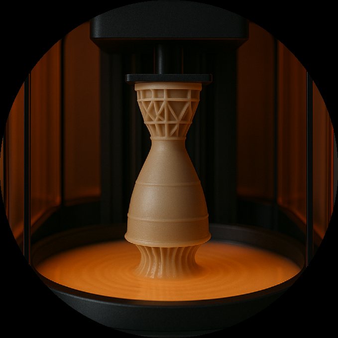
Energy and gas turbines
Ceramic casting cores for blade and vane cooling passages, in larger swept build envelopes.

Materials science
Formulations across a range of viscosities, including filled, engineering and ceramic-loaded resins.

Repair and reuse
Replacement parts that keep products in use instead of in landfill.
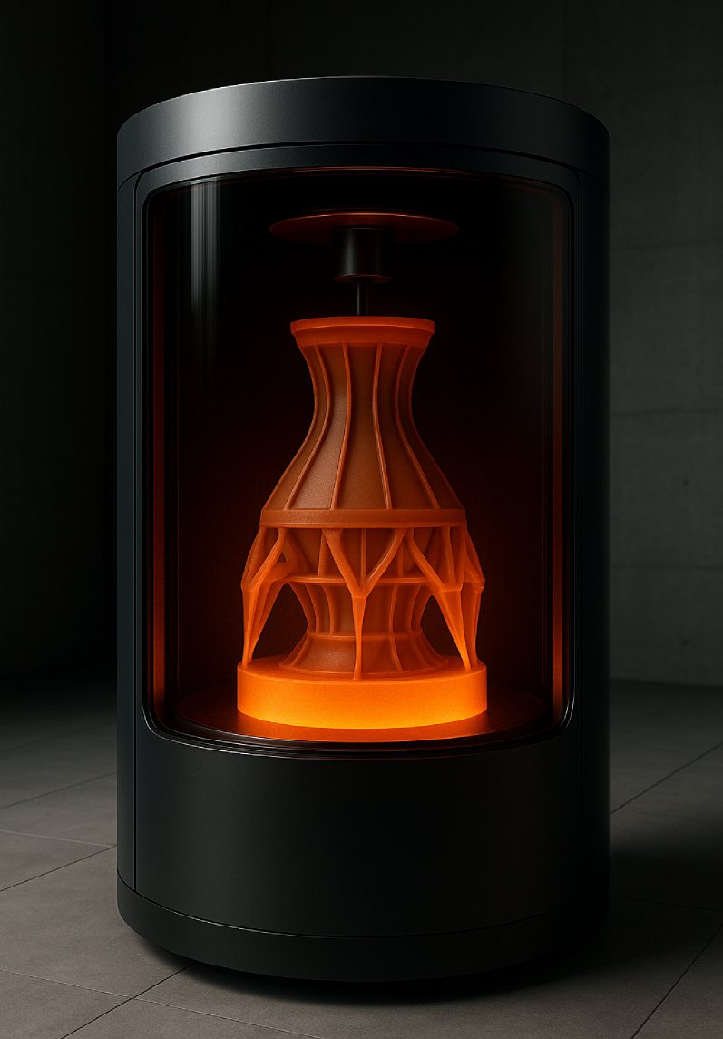
Re-industrialization
Regional, on-demand production closer to the people who need it.
Application images are concept renders.
14 · Patents
Intellectual property
Heliolithography is protected by a growing patent portfolio, with U.S. and international grants and further applications in the pipeline. The founding patent, US 9,321,215, claims priority to a provisional application filed March 12, 2013 and issued April 26, 2016. The process is patented and licensed. It is not open source.
OM is independent. It developed heliolithography on its own, is not affiliated with any university, and is not owned by any other company. All OM intellectual property is owned by OM.
OM’s work also appears in the wider continuous-printing patent record. Carbon’s US 10,589,512 discusses Kurt Dudley’s international spiral-buildup disclosure (WO 2014/165265) in describing rotation as assisting resin delivery. That is documented technical consideration of OM’s work in a closely related problem area, not evidence of commercial adoption.
On the public record
- Mar 12, 2013Provisional application 61/778,285 filed: the priority date for 3D printing using spiral buildup.
- Jul 2, 2014Fabbaloo reports on Orange Maker’s heliolithography process.
- Oct 9, 2014International spiral-buildup disclosure published as WO 2014/165265.
- Apr 26, 2016US 9,321,215 granted.
- Cited in the fieldCarbon’s US 10,589,512 discusses the spiral-buildup disclosure in the context of rotation and resin delivery.
- Sep 10, 2024US 12,083,744 granted for encoded, traceable printed parts.
15 · Status
Development status
OM’s current view of where each capability stands. “Demonstrated” means shown in OM’s lab systems or prototypes; “patented” means covered by an issued patent; “concept” means a design direction to be developed with partners.
| Capability | Status | Notes |
|---|---|---|
| Rotational spiral buildup | DemonstratedPatented | Lab prototypes since 2013–2014; US 9,321,215 and family. |
| Prototype rate of 10 layers/s | Demonstrated | Prototype demonstration; depends on geometry, material, dose and configuration. |
| Non-circular parts | Demonstrated | Rectangular geometry printed by rotation. |
| Radial cure zones and resin channels | DemonstratedPatented | Prototype with illuminated radial zones and channel structure. |
| High-viscosity materials | Patented | US 10,150,247. |
| Laser diode and VCSEL curing | Patented | US 11,141,908 and US 11,958,235. |
| Photosynthesis dual-cure | Demonstrated | Shown in OM’s lab (2020). |
| Ceramic casting cores | In development | Process development for highly loaded ceramic resins; casting validation with partners. |
| Tiled projector light engines | Concept | Route to more optical power over larger areas. |
| Encoded parts | Patentedcontinuation pending | US 12,083,744; US 2025/0214301 A1. |
| Scaling to six-foot builds | Concept | Benchtop architecture designed to scale (2019). |
16 · Working with OM
Working with OM
OM does not sell printers. We license the process and partner with groups whose missions line up with ours, bringing what we have developed, recommended partners, and the team that built it. A typical path has three stages:
- 01Evaluate
A technical review of the platform against your application and roadmap.
- 02Pilot
Your engineers and ours develop it together for your application.
- 03License and scale
Production under license in your field, with OM’s support.
17 · Glossary
Glossary
- Heliolithography (HL)
- OM’s rotational resin 3D printing process: a continuously rotating, rising build platform and light from below cure the part as one helical spiral. From helios, the sun.
- Stereolithography (SLA)
- Resin 3D printing that cures a photopolymer with light, typically one flat layer at a time.
- Vat photopolymerization
- The family of processes, including SLA, DLP and heliolithography, that cure liquid resin in a vat with light.
- Spiral pitch
- The vertical rise of the build platform per revolution.
- Cure zone
- A localized region of the construction area where light cures resin; heliolithography can use one or several radial sectors.
- Resin channel
- A dedicated region between cure zones where fresh resin replenishes the part’s underside as it rotates.
- Inhibition layer
- A thin uncured region at the window that keeps the growing part from adhering, used in continuous resin printing.
- Investment casting core
- A ceramic insert that defines internal passages in a cast metal part, removed after casting.
- Peel force
- The force needed to separate a freshly cured layer from the tank film in layer-by-layer SLA.
- VCSEL
- Vertical-cavity surface-emitting laser, a semiconductor laser that can be built in dense arrays.
- Encoded part
- A printed part with embedded material that carries identifying or manufacturing information.
18 · FAQ
Frequently asked questions
What is heliolithography?
Heliolithography is a rotational resin 3D printing process invented by OM (Orange Maker). The build platform rotates continuously while it rises, and light from below cures resin along one continuous helical path, so the part grows as a single spiral instead of a stack of flat layers.
How is heliolithography different from SLA?
Conventional SLA cures one flat layer, then stops to peel, lift and recoat before the next. Heliolithography has no layer-by-layer cycle: the part rotates and rises continuously while it is cured. The main limits become cure rate and rotation speed.
What materials can it use?
Light-curable photopolymer resins, across a wider range of viscosities than layer-by-layer systems, including thicker materials than other systems can process.
Is heliolithography open source?
No. Heliolithography is patented and licensed by OM.
Does OM sell printers?
No. OM licenses the technology and partners with printer makers, manufacturers, application companies and materials partners.
How fast is heliolithography?
OM prototypes have demonstrated rates of 10 layers per second. Actual rate depends on geometry, material, cure dose and machine configuration. With no peel cycle, the limits are cure rate and rotation speed.
Can a rotational printer make parts that are not round?
Yes. The build platform rotates but the part does not have to be round; OM prototypes have printed rectangular geometry by rotation.
Can it print ceramics?
The architecture is designed to handle highly loaded ceramic resins through replenishment channels and rotational transport. OM is developing ceramic casting cores for gas-turbine blades and vanes with the whole casting route in mind.
Can printed parts be traced?
Yes. OM has patented a method for encoding printed parts with embedded magnetic or spectral-emitting particles that carry information about when and how a part was made and with what materials, supporting serialization, anti-counterfeiting and traceability.
Why is 3D printing described as the physical side of AI?
AI can design a part in minutes but cannot make one. Robots are how AI reaches the physical world, and a 3D printer is a robot built for making things. Faster, more capable printing shortens the path from design to part.
Is OM affiliated with a university or another company?
No. OM built heliolithography independently. It is not affiliated with any university and is not owned by any other company. All OM intellectual property is owned by OM.
Who founded OM?
OM (Orange Maker) was founded by inventor Kurt Dudley and Doug Farber. The first heliolithography patent application was filed on March 12, 2013.
